Design for Assembly:
|
|
|
Animation showing the final deliverable for the thesis. It is a software tool built as a plugin in Rhino 3D that helps users to design an interlocking frame system.
Movie info: QuickTime, 1 minutes and 15 seconds, 400x300 pixels (3.4Mb) |
|
Thesis OverviewDesign for assembly: a computational approach to construct interlocking wooden frames (June, 2012) This thesis explores the computational process of generating and constructing interlocking frames. Its outcome delivers a sophisticated software tool that creates a three dimensional interlocking pattern, analyzes the intersecting conditions between members, and immediately provides instruction of its assembly sequence in animated visualization. An interlocking frame is a system that consists of short members spanning on a large surface where members lock each other at their mid-spans by simple notches. Such a system should be designed with consideration of its assembly sequence, as a static interlocking form may be described but impossible to assemble in any sequence. Given a three dimensional digital model of an interlocking frame, the feasibility of the disassembly sequence can be assessed by analyzing the geometric contact constraints between each member. The assembly sequence can then be obtained by reversing the disassembly sequence, and helps a designer to evaluate different options in the earlier stage of design. The proposed tool uses the genetic algorithm and graph searching algorithms to find optimized notching configurations that guarantee an assembly sequence. It can analyze various types of assemblies defined by planar surface contact constraints, and has a potential for further development into a versatile, automated 4D simulation tool. |
 |
Fig. 1 (Click on the image to enlarge.) Steps to design and construct an interlocking frame. |
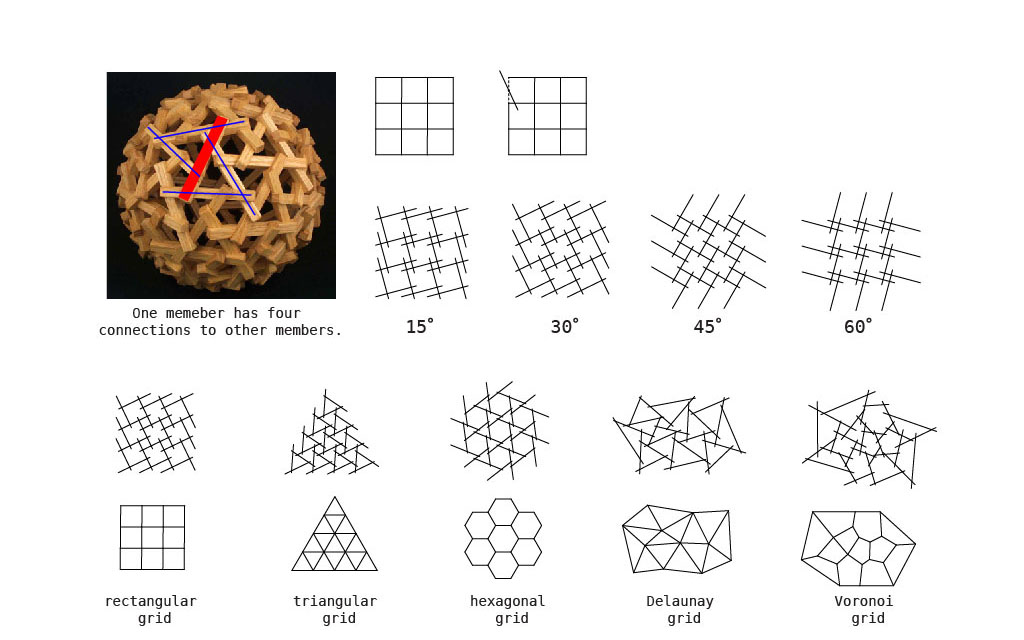 |
Fig. 2 (Click on the image to enlarge.) The method to generate interlocking patterns from grid systems.
|
 |
Fig. 3 (Click on the image to enlarge.) Possible intersecting conditions between two members. The first two conditions needs to be enforced in the system because of fabricability concerns. |
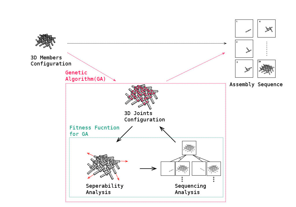 |
Fig. 4 (Click on the image to enlarge.) Using Genetic Algorithm to generate optimized notching configurations and assembly sequence.
|
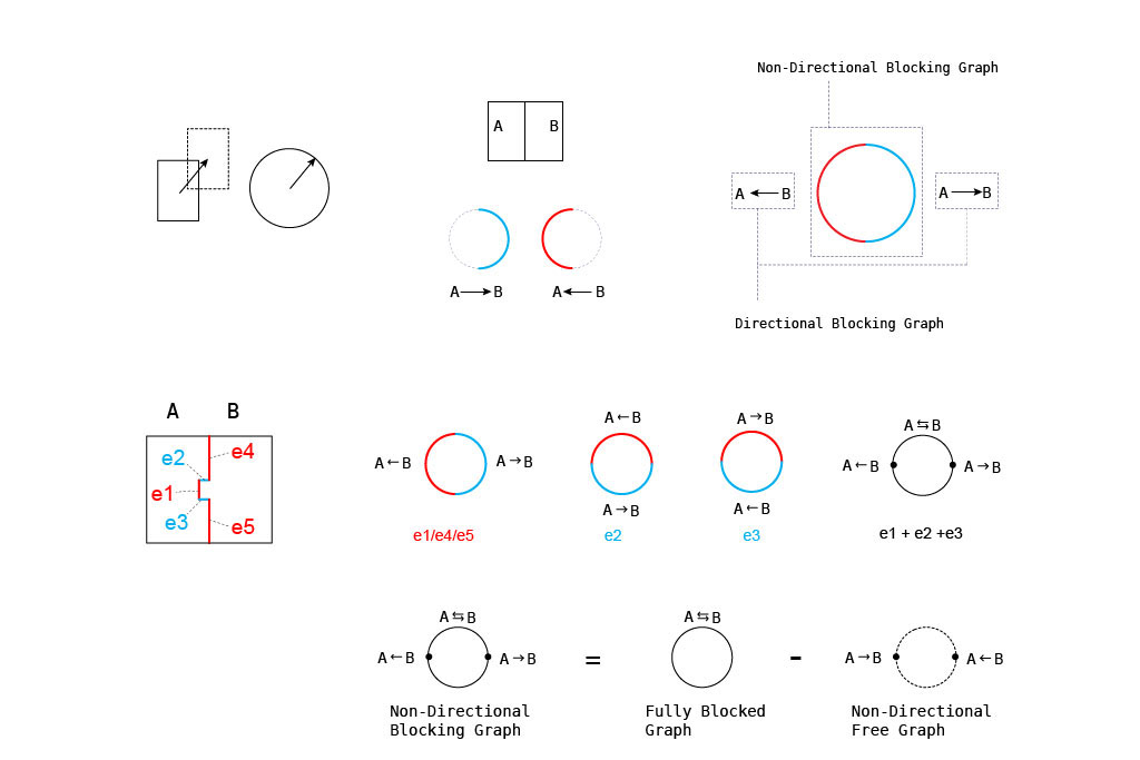 |
Fig. 5 (Click on the image to enlarge.) Using Non-Directional Blocking Graph and Directional Blocking Graph to describe interlocking properties.
|
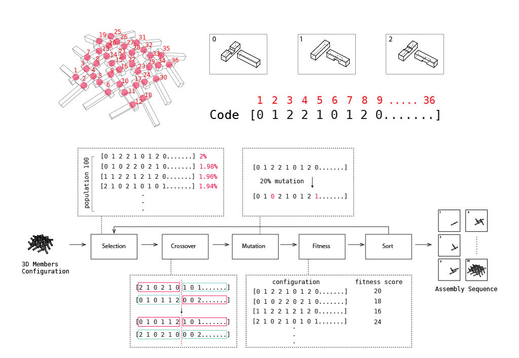 |
Fig. 6 (Click on the image to enlarge.) Encoding the joint configuration for Genetic Algorithm.
|
 |
Fig. 7 (Click on the image to enlarge.) Using various tree searching algorithm to determine the fitness for Genetic Algorithm.
|
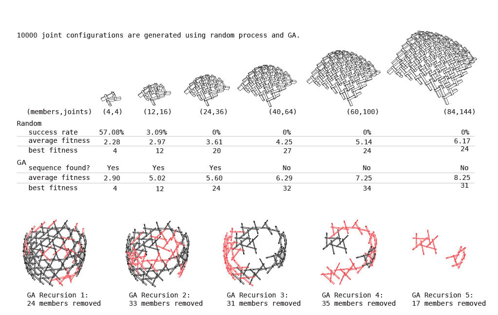 |
Fig. 8 (Click on the image to enlarge.) Using recursive Genetic Algorithm to generate assembly sequence large assembly.
|
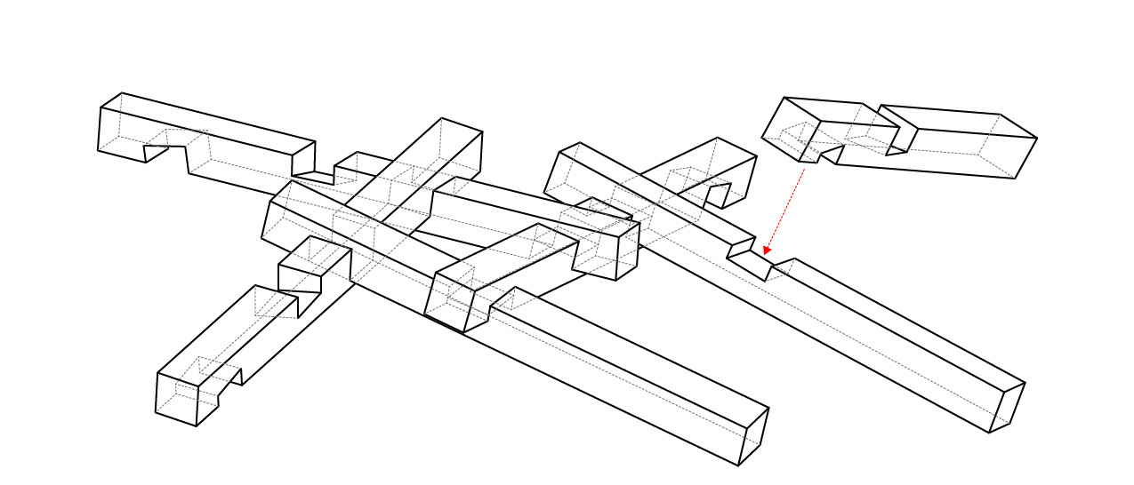 |
Fig. 9 (Click on the image to enlarge.) Joint notching detail
|
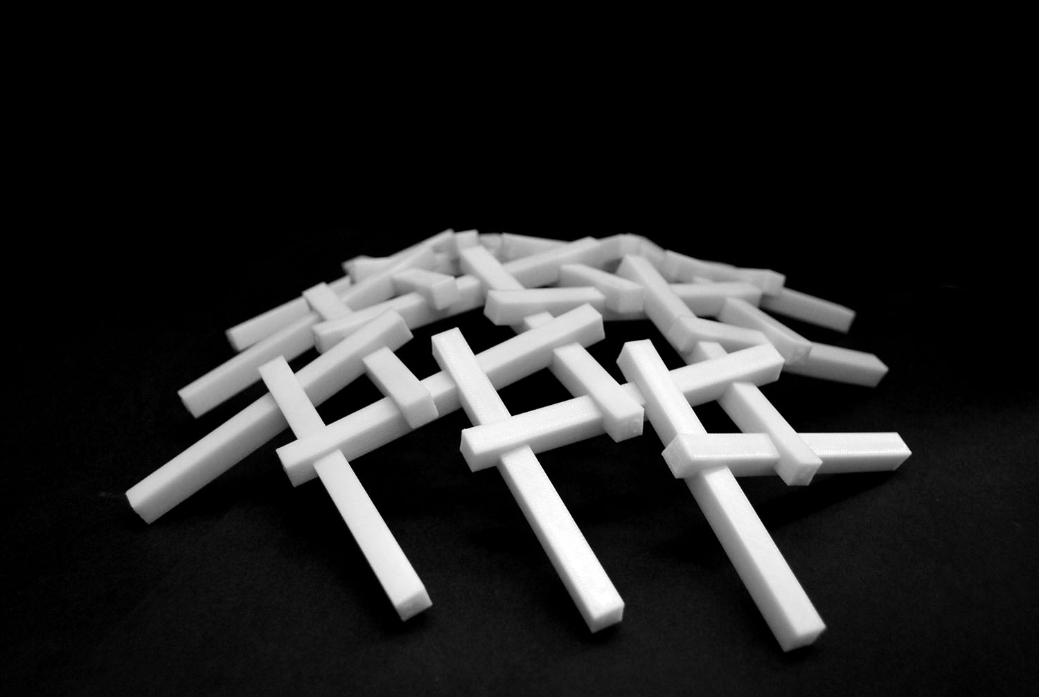 |
Fig. 10 (Click on the image to enlarge.) Each member is 3d printed and assembled into an interlocking frame system.
|
| Animation of running the recursive Genetic Algorithm to generate an 144-member assembly. | |
| Animation of the program that generates disassembly sequence for models defined by planar contact constraints. |